

I have a number of sections following the rules written up in the Berrett Hill On30 sectional guidelines. These are the sections and their count to date:

The basic 90 degree curve section. Curved Sections with 26" radius track have a 30" outside facia radius and an 18" inside facia radius. That makes this unit fit in a 2'-6" square in a plan view.
6 of these are in operation.

The 60 degree section, similar to the 90 degree section above.
2 are complete.

And the 30 degree section.
2 are complete.

The 2 foot straight section. It can be turned end for end to provide a left or right through track.
2 are complete
The 2 foot "S" curve section. These are either right or left handed.
1 left and 1 right are complete
4 foot sections can be 4 foot straight or 4 foot "S" curve designs.
none of these are currently built
The 4 foot section with a spur track is a straight design superimposed on an "S" curve design.
1 left and 1 right are complete
A spur track section may be used in three different ways:
-
 The straight track may be used as the through track and the crossed-over track used as a spur.
 -
The crossed-over track may be used as the through track and the straight track used as a spur.
-
Two units may be used together for use as a through siding.
The 4 foot by 18 inch offset section.
4 of these sections are complete
Two of these offsets when paired with two 90 degree curves will create a "lollypop" shape.
The 4 foot by 18 inch offset with reverse loop connector section is really just a modified version of the offset module above.
Two of these are complete, one left and one right.

The 30 degree reverse loop connector. A customized curved section connects to the section above with a similar turnout and a tangent track.
Two of these are complete, one left and one right.
This is how the two modules above can be arranged using a bridge track to complete a reverse loop.

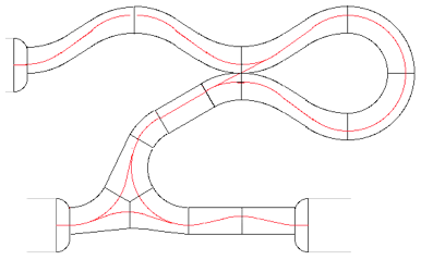
The 60 degree fork section. A peculiar shape is formed by a 60 degree turn combined with a 4-1/2" offset. This creates a fork to a divergent route.
Three of these are complete, one left and two right.
The shape of the 60 degree fork section makes more sense when assembled into a wye. The wye is 5'-2" wide and about 4'-6" deep. The two bottom exits are opposite and in-line with each other, while the top exits at 30 degrees from perpendicular.

Finally, the 6 inch adapter section will correctly mate the Berrett Hill sections with the Mid-Atlantic Standard endplate. Peco code 100 track is used here, a one inch setback for bridge rails and a 6" straight track complies with the module requirements of the Mid-Atlantic standard.
Five of these are complete.
Here is an example of a layout built to connect other modules. This grouping is quite compact, about 16 feet wide by 10 feet top-to-bottom. Other sections could be fit in if the space can be arranged, like straight lengths added in to extend the loop. "T" or "L" shapes can be created if they fit the space better. The isles as shown are 3-4 feet wide.
All turnouts are operated by Tortoise machines controlled by NCE Switch-It DCC controllers fitted with local manual push buttons.
I use NCE controls. I have two 5 amp Power Pro supplies and three handheld controllers. I have 7 network jack panels mounted to clamp under the facia. All primary wiring is twelve gauge with barrier strips and PowerPole pig-tale connectors.

Note: Several less “geometric” modules have been completed since this was first written. The 10 foot long station sectional was followed by the Hill and Mountain modules. A flour mill module and engine terminal module are each partially completed. A trestle and a mountain-side module as well as some large radius curves are planned.